Titan 440 Parts Diagram Explained Step by Step
Introduction
Alright, imagine we’re on a phone call and you’ve just asked me, “Can you explain the Titan 440 parts diagram in a way that actually makes sense?” That’s exactly how this article is written. No robotic tone, no over-complicated language—just a clear, step-by-step explanation like one professional explaining it to another.
The Titan 440 paint sprayer is a workhorse. Contractors love it, DIY users trust it, and painters rely on it day after day. But when something goes wrong, most people panic—not because the machine is bad, but because they don’t understand the Titan 440 parts diagram. Once you understand how the parts connect and work together, troubleshooting becomes much easier.
In this guide, we’ll break down the Titan 440 paint sprayer parts, explain their function, and help you understand the diagram step by step. By the end, you’ll be able to look at a Titan 440 parts diagram and instantly know what’s what and why it matters.
Understanding the Titan 440 Parts Diagram Basics
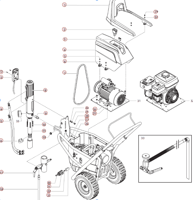
When you first look at a Titan 440 parts diagram, it can feel overwhelming. There are lines, labels, part numbers, and exploded views that look more like engineering blueprints than something for everyday users. But once you understand the logic behind it, everything starts to click.
The diagram is designed to show how every component fits together inside the sprayer. Each part is separated visually so you can see its position, connection points, and relationship with other components. This is called an “exploded view,” and it’s extremely useful for repairs and maintenance.
Think of the diagram as a map. Instead of guessing where a leak or pressure issue might be coming from, the Titan 440 parts diagram shows you exactly where each part lives. This saves time, reduces mistakes, and helps you order the correct replacement part the first time.
Main Pump Assembly in the Titan 440 Paint Sprayer
The pump assembly is the heart of the Titan 440 paint sprayer. If you’re explaining the machine to someone, this is always where you start. In the Titan 440 parts diagram, the pump assembly is usually front and center for a reason—it does most of the heavy lifting.
This assembly includes the piston rod, inlet valve, outlet valve, and seals. Together, these parts create the pressure needed to pull paint from the bucket and push it through the hose. If your sprayer loses pressure, pulses, or won’t prime, the issue is often somewhere in this assembly.
Understanding how these parts connect in the diagram helps you identify wear points. Seals and valves wear out faster than metal parts, and the Titan diagram makes it easy to see which seal matches which valve. That’s why professionals always check the pump section first when diagnosing problems.
Motor and Drive System Explained Clearly
The motor and drive system is what powers the pump. In the Titan 440 parts diagram, this section usually sits behind the pump assembly and connects through gears or a crank mechanism. It might look complex, but its job is actually simple—convert electrical energy into mechanical movement.
The electric motor turns a drive shaft, which then moves the piston inside the pump. If the motor runs but the sprayer doesn’t build pressure, the diagram helps you trace the issue from the motor to the drive components. This is where understanding the layout really pays off.
Over time, drive components can loosen or wear out. The diagram shows you exact part numbers for gears, bearings, and couplers, making replacement straightforward. Instead of replacing the entire unit, you can fix only what’s needed.
Fluid Section and Paint Flow Path
Now let’s talk about paint flow. One of the most useful parts of the Titan 440 parts diagram is how it visually explains the path paint takes through the machine. From the suction tube to the spray gun, every step is clearly mapped.
Paint enters through the inlet system, passes through filters, moves into the pump, and exits through the outlet fitting into the hose. If you ever experience clogging, spitting, or uneven spray, the issue is usually somewhere along this path.
By following the diagram, you can isolate the problem area instead of cleaning everything blindly. For example, if paint reaches the pump but not the hose, you know to focus on the outlet valve or filter. This saves time and reduces unnecessary part replacements.
Filters and Valves Breakdown
Filters and valves might seem like small components, but they play a massive role in performance. In the Titan 440 paint sprayer parts diagram, these parts are clearly labeled because they require frequent inspection and replacement.
The inlet valve controls how paint enters the pump, while the outlet valve manages pressure as paint exits. Filters prevent debris from damaging internal parts or clogging the spray tip. When any of these fail, spray quality drops instantly.
The diagram helps you see how valves and filters are layered together. This is especially helpful when reassembling after cleaning. One incorrectly placed seal can cause leaks or pressure loss, and the diagram ensures everything goes back exactly where it belongs.
Hose, Gun, and Tip Connections
Moving outward from the sprayer body, the Titan 440 parts diagram also shows hose, gun, and tip connections. These external parts are just as important as internal components, especially for spray consistency.
The hose connects to the outlet fitting, which is designed to handle high pressure. Any mismatch or worn fitting can cause leaks or dangerous pressure loss. The diagram helps you confirm compatibility and correct assembly.
Spray gun and tip parts are often replaced more frequently. The diagram shows thread types, seals, and connectors, making it easier to avoid cross-threading or using incorrect adapters. This is critical for both safety and spray quality.
Electrical Components and Safety Features
Electrical components might not be the first thing users look at, but they’re clearly outlined in the Titan 440 parts diagram. This includes the power switch, wiring, capacitor, and grounding components.
These parts ensure the motor runs smoothly and safely. If the sprayer won’t turn on or shuts off unexpectedly, the diagram helps you trace electrical connections without guesswork. You can quickly identify whether the issue is the switch, wiring, or motor itself.
Safety features are also part of this section. Proper grounding and overload protection prevent damage to the machine and reduce the risk of electrical hazards. Understanding these components adds an extra layer of confidence when working on the sprayer.
See also: Top Reasons to Study a Master of Science in Data Science in Singapore’s Thriving Tech Hub
Frame, Wheels, and Structural Parts
The frame and wheels might seem basic, but they’re essential for portability and stability. In the Titan 440 paint sprayer parts diagram, these components are usually shown separately from the mechanical parts.
The frame holds everything in alignment. If it bends or loosens, internal components can shift, causing wear or vibration issues. The diagram helps you identify mounting bolts and brackets that keep the sprayer stable during operation.
Wheels and handles make the unit mobile on job sites. Knowing the correct part numbers for these components is helpful when replacing worn wheels or damaged handles, especially for contractors who transport their equipment frequently.
Using the Titan 440 Parts Diagram for Repairs
One of the biggest advantages of understanding the Titan 440 parts diagram is confidence during repairs. Instead of guessing or relying on trial and error, you follow a visual roadmap that shows exactly how parts interact.
This approach reduces downtime. You identify the faulty component, confirm its position in the diagram, and replace only what’s necessary. That’s how professionals keep costs low and machines running longer.
The diagram also helps when ordering parts online. Matching part numbers directly from the diagram eliminates mistakes and ensures compatibility with your specific Titan 440 model.
Conclusion
So if I had to sum this up like I would on a phone call, I’d say this: the Titan 440 parts diagram isn’t just a technical drawing—it’s your best troubleshooting tool. Once you understand how the Titan 440 paint sprayer parts fit together, maintenance becomes predictable instead of stressful.
Whether you’re dealing with pressure issues, leaks, or routine wear and tear, the diagram gives you clarity. You stop guessing, start fixing, and extend the life of your sprayer without unnecessary replacements.
If you work with the Titan 440 regularly, learning its parts diagram is one of the smartest investments of your time. It turns a complex machine into something you fully understand—and that’s where real control begins.